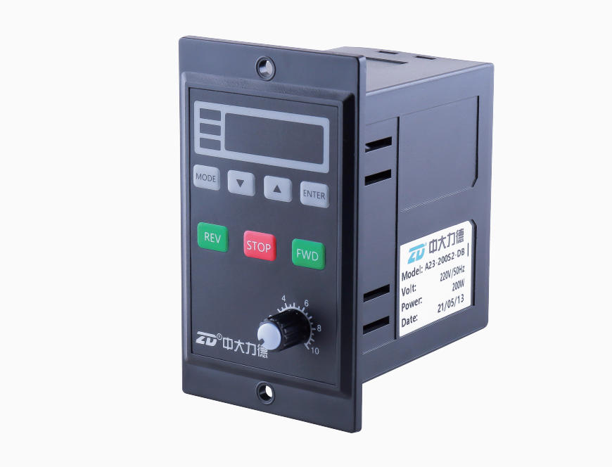
A23 Series Brake-type Digital Speed Control Instruction Suppliers

Home / Products / Motor Driver & Controller / AC Speed Controller / A23 Series Brake-type Digital Speed Control Instruction

Features

● Multi-function and high performance of MCU digital control technology;

● Easy setting with digital display of menu;

● Shown target value can be adjusted through magnification setting;   

● Slow acceleration & deceleration and power-off electromagnetic braking;

● External keyboard and switch are available;

● Easy and safe speed controlling and function of adjusting motor speed deviation;

● Built-in run capacitor;

● Automatically recognize input power frequency;

● Locked rotor protection to protect motor or speed controller to be burned due to locked rotor.


 Panel Introduction

Name Function  
Indicator Light For showing running status
Digital Tube 4-digital tube is used to show parameter value and set value
MODE Enter into or exist from MENU
ENTER Show and confirm set value
▼/▲ Adjust parameter when it is under the condition of button controlling; adjust set value under the mode of MENU
FWD/REV Forward or reverse when it is in the panel control mode, while change the digital when it is in the MENU mode
STOP Stop the running; error reset
Knob Change the specifications when it is in the knob control mode


Model Number/Function Specifications Table

Model Number
ZDRV.A23-□□S2-DB
Model Defintion
Model Type
ZDRV
Model Series
A23
Applicable Motor Power
6W / 15W / 25W / 40W / 60W / 90W / 120W / 140W / 200W
Power Supply
S1 Single phase 110V±10%; S2 single phase 220V±10%
Function
D with digital display; B with brake
Usable Motor Type
Speed Control and Electromagnetic Brake Motor
Installation Method
Panel type
Motion Control Function
Controlled by panel or external switch; speed control; slow acceleration; slow deceleration; eration; slow deceleration;
power-off electromagnetic braking
Speed Control Methods
▲▼ Button on panel; knob on panel
Speed Control Range
50Hz: 90-1400r/min; 60Hz: 90-1700r/min
Run Capacitor
Built-in type
Input Power Supply
Single phase 220V±10%; 50Hz-60Hz
Usage Environment
Environment temperature: -10
℃~+40℃ (no freezing); environment humidity: less than 85% (no condensation); elevation less than 1000m


 Outline & Installation
Unit:mm


Rotation Direction Control
1、Menu Setting: change the operation control mode F-03 into “2”or “3”
Controlled by external switch.
2、If forward (motor), connect “FWD” and “COM”; If reverse (motor), connect “REV” and “COM”.
● Motor Selection
 
The power of a speed control motor should be the same with that of a speed controller.
Pay attention to the power on model No. of the speed controller and make sure that it is same with the power of amotor.
● Power Supply
The voltage of the power supply should be the same with that of a speed controller.
QF is a circuit breaker, it can protect the speed controller and the motor in case of short-circuited. 
     
Power Supply
Motor Power
QF Current Specifications
220V 6-90W 1A
220V 120-200W 2A
110V 6-90W 2A
110V 120W 4A

FWD, REV is controlled by PLC
PLC Output Method: NPN or drain transistor output;
Menu Setting: change the operation control mode F-03 into “2” or “3”
Controlled by external switch.
FWD, REV is controlled by sensor (Photoelectric switch etc.)
Switch Output Method: 3-wire type NPN transistor output;
Menu Setting: change the operation control mode F-03 into “2” or “3”
Controlled by external switch.


Driver Menu

Function Codes Table (R/W: Readable/Writable; RO: Read Only)

Function Code Name Detailed Parameter Description Setting Range Default Value Change
F-01
Shown Content
1: Motor speed setting value
2: Magnification speed setting value
1~2 R/W
F-02
Magnification Setting
Magnification value 1.0~999.9
Magnification speed setting value=motor speed setting value /magnification value
1.0~999.9
1.0
R/W
F-03
Magnification Setting
1: By operation panel
2: By external switch, STOP button on panel is invalid
3: By external switch, STOP button on panel is valid
1~3
R/W
F-04
Rotation Mode
1: Allow to forward and reverse
2: Allow to forward, disallow to reverse
3: Allow to reverse, disallow to forward
1~3
R/W
F-05
Rotation Direction
1: No converse 
2: Converse
1~2
1 R/W
F-06
Speed Control Mode
1: UP/DOWN button speed control on panel
2: Knob speed control on panel 
1~2
1 R/W
F-07
Max. Speed
F-08(Min. speed)~1700
Limit Max. speed (exceed the limitation) to protect it from damage 
F-08~1700
1400 R/W
F-08
Min. Speed
90~F-07(Max. speed)
Limit Min. speed to protect it from unstable motor running
90~F-07
120 R/W
F-09
During the start-up of forwarding and after releasing the electromagnetic brake, the latency time for motor starting
0.0~2.0s: If the acceleration is too fast, it could increase it into 0.1s

0.0~2.0
0.0 R/W
F-10
Acceleration time when start-up of forwarding
0.1~10.0s:The longer, the more stable of motor start-up and vice versa; the shorter, the less stable of motor start-up and vice versa.
0.1~10.0
1.0 R/W
F-11
Stop Method when Forwarding
1: Power-off electromagnetic braking
2: Free stop
3: Decelerate to stop
When select power-off electromagnetic braking, the motor will stop at once and brake; when select to automatically decrease and stop, if the motor stops fast, a decreasing and stopping mode can be selected.
1~3
1 R/W
F-12
During the stopping of forwarding, the latency time for power-off the electromagnetic brake
0.0~5.0s:(F-11=1 is valid) When motor stops, during the set time, it will decrease automatically first and then stop.
0.0~5.0
0.0
R/W
F-13
Stop Deceleration Time for Forward Rotation
 0.1~10.0s:(F-11=3 is valid)  0.1~10.0
1.0
R/W
F-14
During the start-up of reversing and after releasing the electromagnetic brake, the latency time for motor starting
0.0~2.0s:If the acceleration is too fast, it could increase it
into 0.1s
0.0~2.0
0.0
R/W
F-15
Start-up Acceleration Time for Reverse Rotation
0.1~10.0s
0.1~10.0
1.0
R/W
F-16
Stop Method for Reverse Rotation
1: Power-off electromagnetic braking
2: Free stop
3: Decelerate to stop
When select power-off electromagnetic braking, the motor will stop at once and brake; when select to automatically decrease and stop, if the motor stops fast, a decreasing and stopping mode can be selected.
1~3
R/W
F-17
During the stopping of reversing, the latency time for power-off the electromagnetic brake
0.0~5.0s:(F-16=1 is valid) When motor stops, during the set time, it will decrease automatically first and then stop
0.0~5.0
0.0
R/W
F-18
Stop Deceleration Time for Reverse Rotation
0.1~10.0s:(F-16=3 is valid) 
0.1~10.0
1.0
R/W
F-19
Power Supply Frequency Setting
1: Driver self-detection
2: Supply power frequency 50Hz
3: Supply power frequency 60Hz
1~3
1
R/W
F-20
Reset
1: Do not recover
2: Recover
1~2
1
R/W
F-21
Current Adaptive Power Frequency
50: Adapt to 50Hz AC power supply
60: Adapt to 60Hz AC power supply
50,60
**
RO
F-22
Program Version
   
*.**
RO

Trouble-shooting & Status:
  Name Cause How to Solve
Error Code
E.LOC
Motor rotor locked error
Check the connection of speed controller and motor; check mechanical error; press STOP button to reset
E.EEP
Data saving error
Re-power to clear the alarm
Prompt Code S.run
Motor is running, any modification is prohibited.
Press STOP button and then modify
S.not.
Function of the button is currently invalid.
Modify F-03, F-04 or F-06 function code
S.Err
Driver is currently having an error.
Clear the error and re-start
S.loc
The button is locked.
Press both DOWN and ENTER buttons at same time


MENU Change
For safety, please stop the motor and then modify. Modification is not allowed when the motor is running.

Note: When the driver is running or stopping, press MODE and ENTER buttons at the same time,the buttons will be locked and won't have the functions
to control the motor or enter the MENU etc.;and then press MODE and ENTER buttons at the same time, it will release the lock.

 
User Instruction
○ Check if the package is ok, nameplate is consistent with purchased model, and if you received all the accessories.

   Accessories: 1 Operation instruction; 2 bolts (M4*10).

○ Installation, connection and inspection should be done by professional engineers.

○ Before first-time usage, do run without load first to check if everything is working normally and adjust the using specification.

○ Correctly wiring according to this operation instruction or label at the back cover to avoid error or danger.

○ Do not disassemble the device or change the wiring when power is on, it may cause electric shock.

○ Do not use in explosive environments, flammable gas, corrosive environments and anywhere easy to get wet or around combustibles.

○ Avoid continuous vibration, over impact, or it may cause damage to the device.

○ Do earthing.

○ Under normal operation of the motor, sometimes the surface temperature of the motor case will exceed 70°C, therefore, please paste a warning notice (refer to the right drawing) in case people may touch the motor!


Ningbo Zhongda Leader Intelligent Transmission Co., Ltd is a High-tech public enterprise specializing in research & development, manufacture, sales and service of motor driver, micro motor and high precision gearbox. August 29, 2017, Zhongda went public in the Shenzhen Stock Exchange SME board A-shares (stock code 002896), As a one of the powerful A23 Series Brake-type Digital Speed Control Instruction manufacturers and A23 Series Brake-type Digital Speed Control Instruction suppliers in China. our company Participated in the drafting of 7 National Industrial Standards, Own 90 national patents, Have Zhejiang provincial enterprise R & D Center, our A23 Series Brake-type Digital Speed Control Instruction and other products are widely used in industrial robots, intelligent logistics, new energy, machine tools and other fields, as well as special machinery and equipment for food, packaging, textile, electronics, medical, etc. for their differentiated and cost-effective advantages.

No. of Employees: 1,500 employees

Mission: Zhongda realizes the infinite possibilities in automation applications.

Main Business: It is a High-tech public enterprise specializing in research & development, manufacture, sales and service of motor driver, micro motor and high precision gearbox.

Main Products: Micro DC & AC gear motor, small AC gear motor, planetary gearbox, high precision cycloidal gearbox and motor driver, etc.

Tips: Not all gearbox catalogue listed. Feel free to inquire and get latest catalogue. Need solution? We'd like to help.

Show Information

News & Media

How can planetary gearboxes ensure high torque output capability through material selection and heat treatment?

Industry News

How can planetary gearboxes ensure high torque output capability through material selection and heat treatment?

(1) Material selection: Laying the foundation for high strength and reliabilityMaterial is a key factor affecting the load-bearing capacity of gears. ......

When Should You Use a Planetary Gear Motor?

Industry News

When Should You Use a Planetary Gear Motor?

1. High Torque Output Needed in Compact SpacesPlanetary gear motors are ideal for applications where high torque is required, but space is limited. Th......

What is the impact of the accuracy of the gear motor on the performance of the robot?

Industry News

What is the impact of the accuracy of the gear motor on the performance of the robot?

1. Motion controlThe accuracy of the gear motor directly affects the accuracy and reliability of the robot's motion control. High-precision gear motor......

Related knowledge of robot joint reduction motor

Industry News

Related knowledge of robot joint reduction motor

Robot joint reduction gear motor plays a vital role in modern robotics. It is a key component of robot joint motion control. It increases the output t......

Why do geared motors use aluminum housings?

Industry News

Why do geared motors use aluminum housings?

1. Aluminum is lightweight and easy to transport and installAluminum is lighter than traditional cast iron or steel. In practical applications, the in......

What are the key points to pay attention to when installing and arranging the reduction motor?

Industry News

What are the key points to pay attention to when installing and arranging the reduction motor?

1. Vibration and noise controlWhen installing a micro reduction motor, you need to consider the vibration and noise of the equipment. Especially in a ......