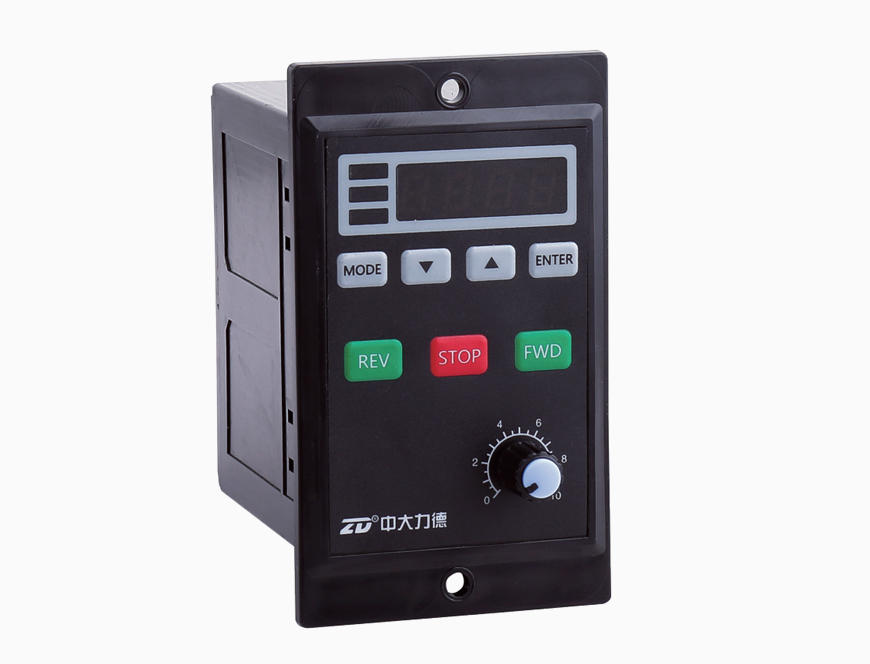
ZF Series Digital Speed Controller Suppliers

Home / Products / Motor Driver & Controller / AC Speed Controller / ZF Series Digital Speed Controller

Features

● Multi-function and high performance of MCU digital control technology;

● Easy setting with digital display of menu;

● Shown target value can be adjusted through magnification setting;    

● Slow acceleration & deceleration are capable;

● External keyboard and switch are available;

● Easy and safe speed controlling and function of adjusting motor speed deviation;

● Built-in run capacitor;

● Automatically recognize input power frequency;

● Locked rotor protection to protect motor or speed controller to be burned due to locked rotor.


 How to Read

Digital Display Panel Type:  


Model Number/Function Specifications Table

Model Number ZF206C(A)
ZF315C(A)
ZF425C(A) ZF540C(A) ZF560C(A) ZF590C(A) ZF5120C(A) ZF6120C(A) ZF6140C ZF6200C
Applicable Motor Power 6W 15W 25W 40W 60W 90W 120W 120W 140W 200W
Applicable Motor Type Speed Control Motor
Installation Method Digital Display Panel Type
Speed Control Methods “▲” “▼” Button on Panel; Knob on Panel
Run Capacitor Built-in Type
Speed Control Range 50Hz:90-1400r/min;60Hz:90-1700r/min
Input Power Single Phase 110V±10%/Single Phase 220V±10%;50Hz-60Hz
Usage Environment -20℃~+40℃(No freezing), Less than 85%(No condensation)

 Outline & Installation
Unit:mm


 Wire Diagram of Speed Controller:

FWD/REV is controlled by PLC
PLC Output Method: NPN or drain transistor output;
Menu Setting: Change the Operation Control Mode F-03 into “2”or “3”
Controlled by external switch.
FWD/REV is controlled by sensor(Photoelectric switch etc.)
Switch Output Method: 3-wire type NPN transistor output;
Menu Setting: Change the Operation Control Mode F-03 into “2”or “3”
Controlled by external switch.

Rotation Direction Control
1. Menu Setting: Change the Operation Control Mode F-03 into “2”or “3”
Controlled by external switch.
2. If forward (motor), connect “FWD” and “COM”;
If reverse (motor), connect “REV” and “COM”.
Motor Selection
The power of a speed control motor should be the same with that of a
speed controller. Pay attention to the power on model No. of the speed
controller and make sure that it is same with the power of a motor. 
Power Supply
The voltage of the power supply should be the same with that of a speed controller.
QF is a circuit breaker, it can protect the speed controller and the motor in case of short-circuited.
Power Supply
Motor Power
QF Current Specifications
220V 6-90W 1A
220V 120-200W 2A
110V 6-90W 2A
110 120W 4A


Controller Menu

Function Codes Table (R/W: Readable/Writable; RO: Read Only)

Function Code Name Detailed Parameter Description Setting Range Default Value Change
F-01 Shown Content 1: Motor Speed Setting Value
2: Magnification Speed Setting Value
1~2 R/W
F-02 Magnification Setting Magnification Value 1.0~999.9
Magnification Speed Setting Value=Motor Speed Setting Value/Magnification
1.0~999.9 1.0  R/W
F-03 Operation Control Mode 1: By Operation Panel
2: By External Switch, STOP Button on Panel is invalid
3: By External Switch, STOP Button on Panel is valid
1~3 R/W
F-04 Rotation Mode 1: Allow to Forward and Reverse
2: Allow to Forward, disallow to Reverse
3: Allow to Reverse, disallow to Forward
1~3 R/W
F-05 Rotation Direction 1: No Converse
2: Converse
1~2 1 R/W
F-06 Speed Control Mode 1: UP/DOWN Button Speed Control on Panel
2: Knob Speed Control On pane
1~2 1 R/W
F-07 Max Speed F-08(Min.Speed)~1700;Limit Max.Speed (exceed the limitation) to Protect it from Damage(50Hz:1400;60Hz:1700) F-08~1700 1400 R/W
F-08 Min. Speed 90~F-07(Max Speed)
Limit Min. Speed to protect it from unstable motor running
90~F-07 120 R/W
F-09 Start-up Acceleration Time for Reverse Rotation 0.1~10.0s 0.1~10.0 1.0 R/W
F-10 Stop Method for Forward Rotation 1: Free Stop
2: Decelerate to Stop
1~2 1 R/W
F-11
Stop Deceleration Time for Forward Rotation
0.1~10.0s(When F-10=2 is valid)
0.1~10.0 1.0 R/W
F-12
Start-up Acceleration Time for Reverse Rotation
0.1~10.0s 0.1~10.0 1.0 R/W
F-13
Stop Method for Reverse Rotation
1: Free Stop
2: Decelerate to Stop
 1~2 1 R/W
F-14
Stop Deceleration Time for Reverse Rotation
0.1~10.0s(When F-13=2 is valid) 0.1~10.0 1.0 R/W
F-15
Power Supply Frequency Setting
1: Driver Self-detection
2: Supply Power Frequency 50Hz
3: Supply Power Frequency 60Hz
1~3 1 R/W
F-16
Reset
1: Do not Recover
2: Recover
1~2 1 R/W
F-17
Current Adaptive Power Frequency
50: Adapt to 50Hz AC Power Supply
60: Adapt to 60Hz AC Power Supply
50,60
**
RO
F-18
Program Version
*.**
RO

Trouble-shooting & Status:
  Name Cause How to Solve
Error Code E.LOC Motor Rotor Locked Error
Check the connection of speed controller and motor; check mechanical error; press STOP button to rest
E.EEP Data Saving Error Re-power to clear the alarm
Prompt Code S.run Motor is running, any modification is prohibited. Press STOP button and then modify
S.not. Function of the button is currently invalid. Modify F-03/F-04 or F-06 function code
S.Err Driver is currently having an error. Clear the error and re-start
S.loc The button is locked. Press both DOWN and ENTER buttons at same time


Menu Change
For safety, please stop the motor and then modify. Modification is not allowed when the motor is running.

Note: When the driver is running or stopping, press MODE and ENTER buttons at the same time,the buttons will be locked and won't have the functions
to control the motor or enter the MENU etc.;and then press MODE and ENTER buttons at the same time, it will release the lock.

 User Instructions
○ Do not use in explosive environments, flammable gas, corrosive environments and anywhere easy to get wet or around combustibles.

○ Avoid continuous vibration or over-impact.

○ Under normal operation of the motor, sometimes the surface temperature of the motor case will exceed 70°C, therefore, please paste a
   warning notice (refer to the drawing below) in case people may touch the motor!

○ No continuously long-time running of the motor under the condition low speed and overload.

○ Do earthing.

○ Installation, connection and inspection should be done by professional engineers.


Ningbo Zhongda Leader Intelligent Transmission Co., Ltd is a High-tech public enterprise specializing in research & development, manufacture, sales and service of motor driver, micro motor and high precision gearbox. August 29, 2017, Zhongda went public in the Shenzhen Stock Exchange SME board A-shares (stock code 002896), As a one of the powerful ZF Series Digital Speed Controller manufacturers and ZF Series Digital Speed Controller suppliers in China. our company Participated in the drafting of 7 National Industrial Standards, Own 90 national patents, Have Zhejiang provincial enterprise R & D Center, our ZF Series Digital Speed Controller and other products are widely used in industrial robots, intelligent logistics, new energy, machine tools and other fields, as well as special machinery and equipment for food, packaging, textile, electronics, medical, etc. for their differentiated and cost-effective advantages.

No. of Employees: 1,500 employees

Mission: Zhongda realizes the infinite possibilities in automation applications.

Main Business: It is a High-tech public enterprise specializing in research & development, manufacture, sales and service of motor driver, micro motor and high precision gearbox.

Main Products: Micro DC & AC gear motor, small AC gear motor, planetary gearbox, high precision cycloidal gearbox and motor driver, etc.

Tips: Not all gearbox catalogue listed. Feel free to inquire and get latest catalogue. Need solution? We'd like to help.

Show Information

News & Media

The difference between hard tooth surface reducer and soft tooth surface reducer

Industry News

The difference between hard tooth surface reducer and soft tooth surface reducer

1. Gear Hardness and MaterialHard tooth reducers boast a tough skin. Gears undergo carburizing or quenching.  Surfaces flaunt HRC58-62 hardness. Cores......

Why can't industrial robots do without planetary gearboxes?

Industry News

Why can't industrial robots do without planetary gearboxes?

1. High torque density and compact designPlanetary gearboxes are compact and can achieve high torque transmission in a small volume. This is crucial f......

10 key factors for selecting the right gear motor

Industry News

10 key factors for selecting the right gear motor

1. Load requirementsUnderstanding the load requirements of the equipment is the first priority. Customers need to know the type of load the motor need......

What are the Applications of Industrial Robots?

Industry News

What are the Applications of Industrial Robots?

In this world of rapidly evolving technology, industrial robotic arms play a pivotal role. Mainly made of actuators, drive systems, and control units,......

How to accurately select the key parameters of planetary gearboxes according to project requirements?

Industry News

How to accurately select the key parameters of planetary gearboxes according to project requirements?

1. Load capacityThe load capacity of the planetary gearbox determines the reliability and life of the equipment under actual working conditions. There......

How to improve the thermal stability of planetary gearboxes?

Industry News

How to improve the thermal stability of planetary gearboxes?

1. Optimize material selectionUsing high-strength, heat-resistant materials is the first step to improve thermal stability. For example, gears and bea......