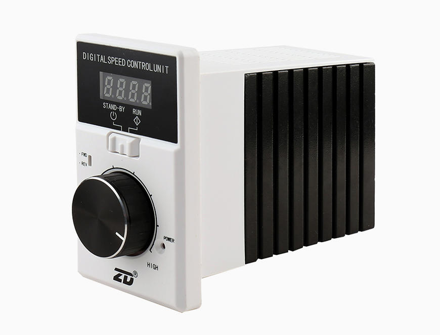
● Digital Display: 4-digit LED tube display: Operation Status, Setting Speed, Operation Speed,Error Indication
● Stable Operation:Speed Closed-loop control (Accuracy±0.5%)
● I/O: 2 NPN digital input interfaces (Forward and Reverse)
1 sinking output interfaces ( Fault Output)
● Speed Setting: Setting speed through knob on the panel.
● Fault Indication & Protection:
Show the fault information after the protection for the fault indication, such as: under voltage, over voltage, over current, over load, locked rotor, short circuit, phase shortage, over temperature etc.

|
Mark
|
Introduction
|
Content
|
|
①
|
Company
|
Z: ZD Leader
|
|
②
|
Model
|
BLD: Brushless Motor Driver
|
|
③
|
Version
|
C10:C10 Series
|
|
④
|
Power
|
120: Max. Output Power 120W(24V)、200W(48V)
|
|
⑤
|
Index
|
L:DC24V~48V
H: High Voltage AC 220V
D: With Digital Display
R: With 485 Communication
|
Requirements of Environment
|
Environment Temperature
|
Environment Humidity
|
Altitude
|
Environmental Vibration
|
Protection Degree
|
|
-10℃~ +40℃(No condensation)
|
Less than 85% (No condensation)
|
Lower than 1000 m
|
No continuous vibration or over impact
|
IP20
|
How to Install
| |
|
 |
Installation Steps
1、Open the panel③
2、Insert the driver ① into the assigned position
3、Fix with M4 countersunk head screw(GB68-85)②
4、Press the panel ③ into the assigned position as show in the picture
To prevent explosion, injury and fire, please do not use in explosive environments, flammable gas, corrosive environments and anywhere easy to get wet or around combustibles.
|
The driver will stop once it detects an error and indicates the error code through digital tube at the same time; users can make trouble-shooting
according to the error code. (Remind: Do power off at least for 5 min before trouble-shooting! )
|
Error Code
|
Error Name
|
Error Indication Code
|
Cause
|
How to Solve
|
| 1 |
Hardware Acceleration Overcurrent
|
OCH1
|
1.Low Voltage
2.Low power of Driver
3.Shock Load
4.Short Circuit Between Phase
5.Strong Interference from outside
|
1.Check the input voltage
2.Select driver with large power
3.Check if it is loaded normally
4.Check/Change cable or motor
5.Check if there exists strong interference outside
|
| 2 |
Hardware Deceleration Overcurrent
|
OCH2
|
| 3 |
Hardware Constant Speed Overcurrent
|
OCH3
|
| 4 |
Software Acceleration Overcurrent
|
OC1
|
| 5 |
Software Deceleration Overcurrent
|
OC2
|
| 6 |
Software Constant Speed Overcurrent
|
OC3
|
| 7 |
Overvoltage during Acceleration
|
OV1
|
1.High Input Voltage
2.Speedy Forward and Reverse Switch
3.In the statue of power generation due to external force
|
1.Check the power supply voltage
2.Increase time for forward and reverse switching
3.Add external brake
|
| 8 |
Overvoltage during Deceleration
|
OV2
|
| 9 |
Overvoltage during Running of Constant Speed
|
OV3
|
| 10 |
Busbar Undervoltage
|
UV
|
1.Low Voltage
2.External Power Supply Protection for Fast Acceleration
3.Voltage Drop
4.Driver hardware is abnormal
|
1.Check the input voltage
2.Reduce the speed
3.Error Reset
4.Ask for engineer assisting
|
| 11 |
Motor Overload
|
OL1
|
1.Low Voltage
2.Motor Overpower
3.Rotor Blocked or Load Sudden Change
|
1.Check the input voltage
2.Use rated current of the motor
3.Reduce the load and check the motor and machine
|
| 12 |
Driver Overload
|
OL2
|
1.Low Voltage
2.Overload
|
1.Check the input voltage
2.Change to driver with larger power
|
| 13 |
Error of Hall
|
HALL
|
1.Disconnection of Hall
2.Strong Interference from Outside
|
1.Check the connection of Hall
2.Check if there exists strong interference outside
|
| 14 |
Locked
|
LOCK
|
1.Overload
2.Motor Locked
|
1.Check the mechanical connection of motor
2.Check the wire diagram of motor
|
| 19 |
Current Error
|
CUr
|
1.Driver Hardware Broken
|
1.Change the driver
|
| 27 |
Data Storage Error
|
EEP
|
1.Reach to the MAX quantity for Power-up Clear( PUC)
|
1.Power-on Again
|
| 29 |
Error of Over-current Feedback
|
OCHF
|
1.Driver Hardware Broken
|
1.Change the driver
|
| 30 |
Error of Lack Input Phase
|
POUT
|
1.U/V/W Lack Input Phase
2.Driver Hardware Broken
|
1.Check if U/V/W are correctly conn-ected
2.Change the driver
|


 EN
EN


